Laser Soldering
We have many years experience in the field of laser soldering, whether with one laser source, six laser sources or with the newly developed laser soldering head with eleven laser sources. With the newly developed laser soldering tool instead of using one laser beam, soldering is carried out using six or eleven laser beams coming from different directions. Thereby radiation intensity of potential burns is reduced by a sixth or eleventh.
With the LLW03 laser soldering tool single laser beams can now be optimally aligned with the geometry of the joint to be soldered. All six lenses are fed from separate laser sources that have a maximum output of 10 Watt. Altogether the laser output for soldering is 60 Watt. These laser sources have a tenfold longer life span than previously used high performance diode modules, thereby considerably reducing the operating costs. Through the use of two separate soldering wires the problem of flux disruption is essentially solved.

Diode laser
In order to focus the required energy of 30 W on a focal point with a diameter of 0.8 mm, the beams of numerous individual laser diodes must be bundled onto the focal point (light spot). This is only possible with complex optics (image on the right).
The radiation from the laser diodes is first collimated in one axis by a cylindrical lens. The radiation is then coupled into the light guide through special optics (staircase mirror).

Adaptive laser soldering tool
The "Flex Beam" laser soldering tool developed by Wolf offers the possibility of local and temporal power modulation by allowing the laser beam to be moved along any path over the workpiece as often as required.

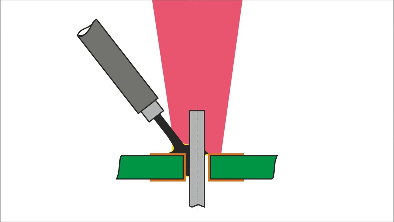
Step 1: Preheating
The solder wire enters the area of the laser beam. The direct irradiation causes it to "melt". There must be no droplet formation. If the laser beam exceeds the pad (soldering eye), the base material can be damaged.
Step 2: Solder feed
The soft, partially melted solder wire melts completely on the PCB or pin. The PCB and pin must be preheated accordingly, otherwise there is a risk that the solder will not be melted off.

Step 3: Hold
The wire largely melts in the existing melt. The melt continuously absorbs energy from the laser beam. There is a risk of damage to neighboring components due to reflected radiation.